
The saga continues...
(Place mouse cursor over images for additional insight!)

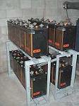
This project began unexpectedly in the late spring of 2001 when a friend of mine called with the loaded question: "Hey, you interested in some batteries?" Through a friend of a friend who knew somebody at some telcom place (the names have been changed to protect the innocent) who was planning on upgrading their standby systems sometime soon, 36 surplus 2 volt, 660 Ah lead-calcium stationary telco-type wet cells might become available, racks and all! My friend was only interested in 12 cells, so I committed to adopting the remaining 24 cells.

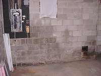
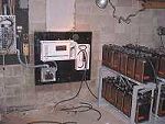
Three months and one dumpster later, I had cleaned out the cellar to make room for the still-tentative battery bank and associated hardware. The cells finally materialized in early fall, and after 8 man-hours worth of work and a couple of new hatchway stair treads, the 3,260 pound battery bank was securely anchored in its new home.
The next step was deciding the battery bank voltage and cell interconnect configuration. Due to the cost of the inverters, I had originally planned to connect the cells in series-parallel for 24V @ 1320Ah. "Phase I" called for the initial installation of a single Trace PS2524 (120V/2500VA output, 24VDC input) sine-wave inverter. This would handle the essential 120VAC emergency loads temporarily until I had enough $$ saved up to implement "Phase II"- the addition of a second inverter series-stacked with the first, providing a total of 5000VA, in a 120/240 volt, 3-wire configuration. The 240V would power the well pump, and the remaining essential (and not so essential) loads would be shared between the two units.
Then, through a stroke of luck, I stumbled across a Trace SW-5548 (5500VA/120VAC output, 48VDC input) sine-wave inverter for sale on Ebay. The SW series inverters are deluxe versions of the PS series units. Although most electrical specs are the same or better, the SW units include a number of built-in features which are extra-cost options on the PS units, such as a battery temperature sensor, LCD display, and programming keypad. A quick call to the seller revealed he was a Trace dealer, and the items he offered were factory-new stock drop-shipped directly to the high bidder!
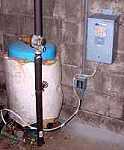
Since the minimum bid on the item was considerably less than the cost of the two smaller units (and required accessories) that I had planned to install originally, it was time to review my design. The only 240 volt load in my home is the well pump, which draws 6A (12A peak) according to my Fluke clamp-on meter. Instead of a pair of series-stacked 2500VA inverters, I could use a single 5500 VA 120VAC inverter and power the well pump using a 20A 120V circuit feeding a surplus 120/240 volt, 5KVA buck/boost transformer. I placed my bid, and 20 minutes later, I was the proud owner of an inverter!
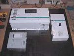
Now that I had the inverter input voltage pinned down, I could begin wiring the battery bank. From that point on, the project proceeded smoothly. I needed a 250A DC-rated disconnect and breaker, and the optional conduit box for the DC side of the inverter. After searching around and pricing these items, I ended up buying them from the same dealer I bought the inverter from! Due to the 136 pound weight of the inverter, it needed a solid mounting surface. The 48"x40" backer board is made of two 3/4" sheets of plywood sandwiched together to form a 1.5" thick sheet, and is anchored to the foundation wall with eight 1/4" toggle bolts. The inverter attaches to the plywood using ten 1" long lag bolts.
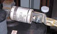
All DC input wiring utilizes 4/0 cable. A 350A current-limiting fuse (specifically rated for protecting solid-state devices) is bolted directly to the positive battery terminal to protect against any possible shorts occurring in the cabling between the battery and the 250A circuit breaker..
On the AC side of the inverter, the input is fed by a 60A breaker and #6 wire from the main service panel. The AC output from the inverter's built-in 60A automatic load transfer relay feeds another 60A breaker, which is part of the manual transfer switch in the GE sub-panel.