VERSION 1
This was my first stab at a quick & dirty sound card interface. An opto-isolator was incorporated to key the radio via the RTS line on the computer's serial port. The sound card's stereo line inputs and speaker outputs were tied together using resistive combiners. Audio level matching was acomplished via simple resistive T-pads. Although it worked, it offered no isolation between computer and radio. I didn't even bother to place the unit in an enclosure- I just used heat shrink tubing to protect it from shorts. Click here to see the schematic.
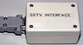
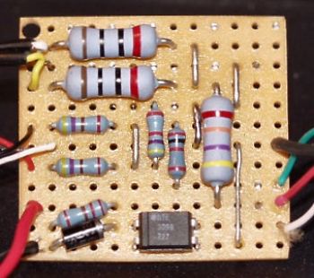
After satisfactory results with Verision 1, I decided to make some modifications. I utilized some surplus 1:1, 600 ohm telco transformers to isolate the audio lines betwen the radio and computer. Although the 600 ohm impedance was not an optimal match to the radio's RX audio line, the transformers, along with the opto-isolated keying line, offered full isolation between both pieces of equipment. TX audio level matching still required the use of a resistive pad. The unit was housed in a small plastic enclosure, and all I/O wiring was made through a DB15 connector. Click here to see the schematic.
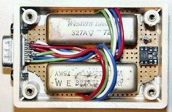
After using Version 2 for almost a year, I started designing Version 3. The opto-isolator keying circuit was retained, along with the DB15 connector for all I/O cabling. The transformer isolation of Version 2 was also retained, but the transformers were upgraded to a pair of professional audio transformers for a higher saturation threshold and wider frequency response. The 10:1 transformers, which were scavanged from an old Shure audio mixer, also provided a better impedance match for the radio's 5K ohm data output.
While using the version 2 interface, I noticed that desktop computers seemed to give the cleanest audio and the least amount of hum when the computer and radio grounds were floated, or isolated from each other. Laptops, on the other hand, seemed to work best when the radio and computer shared a common ground. So I added a ground lift switch which allows selecting between common ground and fully isolated modes.
One drawback I discovered in using version 2 was the need to constantly swap connectors back and forth on the sound card. If I wanted to use the interface, I had to unplug the amplified PC speakers and plug the interface in. If I wanted to listen to music or edit audio on the PC, I had to unplug the interface and plug the speakers back in. To make life easier, I added a 1/8 inch stereo mini jack which is connected in parallel across the DB15 carrying the coumputer soundcard audio output lines. Now, all I have to do is adjust the volume on the amplified speakers. Another advantage to this setup is that I can now monitor the comouter's audio output via speakers (or headphones for portable use) when connected to older radios which do not have a built in monitor function.
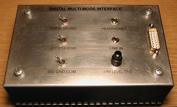
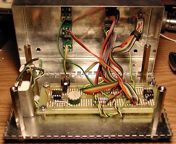
Some other improvements incorporated in version 3 included a 1200/9600 baud input select switch which allows received signals to be fed to the soundcard from the either the radio's 1200 baud audio output or the 9600 baud pre-discriminator output (on radios so equipped). A line-in jack was added to allow decoding audio from receivers not equipped with a PS/2 style data connector, such as scanners. Another 2 position switch was added to allow for selecting left or right channel sound card output to be routed to the radio TX line. Finally, a dual gang miniature 10K pot, scavanged from an old Icom W2A HT, was added to allow for easy TX and RX level setting. Finally, the unit was housed in a metal chassis with with ferrite core chokes on the I/O wiring for shielding and RFI immunity.