MULTI ZONE OVEN CONTROL UPGRADE
A particular production process utilized multiple electrically heated zones. The controls for each zone consisted of a thermocouple feeding a dual channel amplifier, which converted the millivolt level thermocouple signal to a 0-2 volt DC control signal. One amplifier output fed a panel mounted digital volt meter for temperature display. The other amplifier output fed a PID controller board. The PID controller output then fed a trigger board which drove the SCR power controller. To make matters worse, the thermocouple signals were routed through DPDT industrial grade switches which were used to apply the setpoint control voltage to the digital displays for adjusting setpoint. The 250 volt rated contacts on these industrial switches often exhibited resistances high enough to introduce errors in excess of 30 dergrees into the thermocouple signal path, requiring frequent cleaning or replacing.
The calibration process for these controls, which was seven single-spaced pages long, involved individually calibrating the digital temperature display, each T/C converter amplifier, the PID controller, and finally the trigger board. With multiple calibration points on each board, 8 zones per machine, and 5 machines in the production line, calibration was very time consuming! Coupled with a 90 day calibration cycle required by the inherent drift of the aging analog circuitry, calibration alone was responsible for a considerable amount of down time!
I redesigned the control system utilizing eight Watlow 93 PID controllers driving three Watlow DIN-A-MITE power controllers. Each DIN-A-MITE unit controls three zones, which left a spare zone unused for future expansion. The Watlow 93's digital circuitry exhibits zero drift, and the keypad driven calibration cut the required calibration time to no more than 15 minutes per zone! The DIN-A-MITE power controllers require no calibration at all. The calibration cycle, wich was initially set at six month intervals pending performance verification, was finally set to one year intervals.
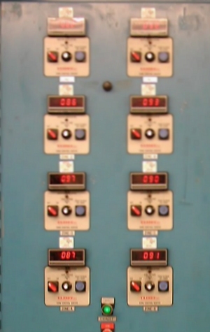
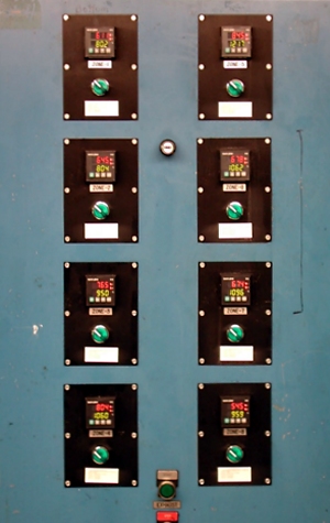
These photos show before (left) and after (right) views of the retrofit. The photos above show views of the front panel. Custom punched black anodized panels were used to cover the holes from the removed switches and potentiometers. The switches below each zone controller are used to enable heating of that zone. The switch handles are also illuminated, and are tied into each controller's deviation alarm. When the associated zone is within five degrees of setpoint, the switch illuminates as a READY indicator.
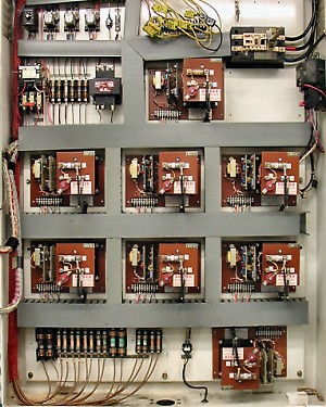
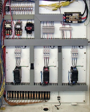
These photos show the cabinet interior. Before modification, the eight power controllers occupied most of the cabinet volume. After the retrofit, the three Watlow DIN-A-MITE power controllers virtually disappear in the seemingly oversized cabinet, even though they are capable of handling an additional zone over the original design!