At one point in my career as an industrial electronics technician, I was responsible for a number of CNC based machines, each of which incorporated multiple rotary optical quadrature encoders. Since the machines were located in a hostile environment, the encoders really took a beating. The design of the machines, however, made it virtually impossible to access any test points where a meaningful encoder performance diagnosis could be made. To save myself a lot of grief, I put together this encoder test jig.
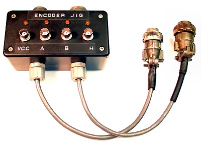
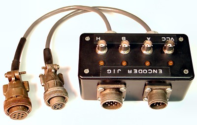
The test jig consisted of 4 LED indicators, 4 BNC style connectors, a pair of male and female 7 pin and 6 pin connectors, half a dozen resistors, and a plastic utility case. The connectors were chosen to match the encoder connectors on the machines I was responsible for. Since some of the machines used 6 pin and some used 7 pin connectors, I used both on the test jig and simply cross connected like signal lines between the 2 pairs. Click here for a schematic diagram.
To use the test jig, the cable connector would be unscrewed from the encoder in question, and screwed into the appropriate chassis connector on the test jig. The matching dongle would then be connected to the encoder. LED's on the test jig monitored the states of the A CH, B CH, HOME/INDEX, and VCC lines. Each of the above signal lines was also connected to it's own BNC jack, making signal monitoring with an oscilliscope a snap!
Another application for the test jig involves using it to bench test encoders. By connecting a power supply to the VCC BNC connector, the DC supply voltage can be injected through the jig to the encoder under test. An oscilloscope can then be used to monitor the encoder outputs.
A quick and easy way to verify the phase relationship between the two encoder channels is to use a dual channel scope in the X-Y mode. Set up the scope for X-Y operation with DC coupling on both channels. Connect the A and B channels of the encoder to the X and Y inputs on the scope. With the encoder powered up, the scope will display a single dot on the screen. Now rotate the shaft, and observe the dot on the scope. The dot will move sequentially through 4 discrete positions, appearing very much like the corners of a box. Rotate the shaft slowly and observe the scope display. The dot on the display should appear to "rotate" clockwise through all four corners when the encoder shaft is turned in one direction, and counter clockwise when the encoder shaft is rotated in the opposite direction. Click here for a short Windows WMV video clip of the resulting scope display.
