
Another project I worked on involved waste heat recovery in an isolated equipment space. A number of old water cooled air compressors had been replaced with a new, energy efficient air cooled model. Although the newer compressor used only a fraction of the energy, it presented a new problem. The excess heat thrown off by the old compressors was more than adequate to heat the equipment space. Since the equipment space was protected by fire sprinklers, the new efficient unit made heating the space to prevent freezing a real concern.
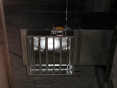
I utilized a Watlow 96 PID controller with 4 outputs to monitor equipment room temperature and control three motorized dampers installed on the air to air intercooler ductwork. Spring return actuators were chosen for fail safe operation. In the event of a controller failure, all dampers returned to their normal positions to maintain cooling air flow to the compressor. The actuator limit switches were also used to interlock the dampers, making it impossible to ever completely shut off exhaust air flow from the intercooler. A motorized damper was installed on the side of the intercooler exhaust duct inside the equipment space, and another motorized damper was installed outside on the intercooler exhaust duct. A third motorized damper was cut into the roof of the equipment room.
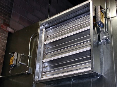
In normal operation, the roof damper remains open allowing outside air to be drawn into the equipment room. The exhaust duct damper remains open to the outside, and the exhaust recirc damper remains closed. The negative pressure created by the intercooler blower draws fresh air into the room, and exhausts heated air outside.
When the equipment space drops below a certain temperature, the recirc damper is opened, allowing for some waste heat to enter the space. If the temperature drops another ten degrees, the exhaust duct outlet damper is closed, redirecting all intercooler waste heat back into the equipment space, while keeping the fresh air inlet damper open for some dilution and convection based mixing.
Another ten dregree drop causes the roof mounted fresh air inlet damper to close, recycling all waste heat into the equipment space. Finally, if the temperature drops another ten degrees, a system monitoring alarm is triggered, notifying key personnel of a potential problem. A small steam based fan coil was also provided as a backup on very cold days or for periods of low air demand, where the compressor run time would not be sufficient to heat the space. Click here for a partial wiring diagram of control system.
The system described above has been in operation for over 4 years, and has proved to be extremely relaible. It has never experienced a failure or malfunction. And the equipment, as well as the equipment room sprinklers are kept well above freezing.