BUILD THE KA1MDA
ICOM CI-V INTERFACE
ICOM's CI-V protocol is based on a relatively simple bi-directional, single-wire TTL level signaling system. The single wire consists of a communications line (DATA) and a ground reference (GND). The DATA line is held high when there is no traffic. As long as the DATA line is high, any device can initiate communication by pulling the line low and sending the Icom attention command (FEFE). When the line goes low, the other devices see this as a BUSY indication, allowing the single DATA line to offer some amount of basic flow control. Multiple devices may connected across the CI-V port in parallel, as long as each device is set up with a unique hex address. All in all, it's quite elegant in it's simplicity.
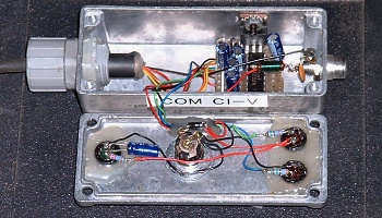
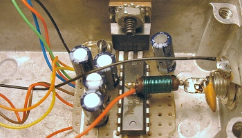
Unfortunately, Icom charges an exorbitant amount of money for what is basically a glorified RS-232 to TTL level converter! However, using the MAX-232 integrated circuit, such a converter can be easily built for under $20. The 2 photos below show the prototype converter I built. I chose to assemble the unit in a metal enclosure for RFI sheilding. The main circuit consists of little more than 2 diodes, 5 capacitors, the MAX-232 IC chip, and a voltage regulator chip.
The converter is normally powered by the host computer's RS-232 port. I added an extra DC power jack to power the interface externally in case the RS-232 port's power was insufficient, although this condition has never occured. I also added 3 LED status indicators for POWER, DATA TX, and DATA RX to aid in troubleshooting connection problems. Originally, the DATA TX LED was wired across the TTL side of the converter, while the RX DATA LED was connected across the RS-232 side of the interface. The design was later simplified with a single DATA LED across the TTL side of the interface, which is reflected in the schematic diagram. If desired, these LED's can be left out all together. As can be seen in the 2 photos above, the interface is quite simple. Component layout and assembly methods are not critical, as can be seen in my liberal use of hot-melt glue to hold the status LED's in place on the prototype's front cover!
Referring to the schematic diagram below, the interface obtains power from the host computer's RS-232 port via the RTS and DTR lines on pins 4 and 20. These lines are always in opposite states- when one is high, the other is low, and vice-versa. The 2 isolation diodes allow only the positive voltage from these 2 pins to reach the voltage regulator. The extrnal power connector also feeds the voltage regulator via its own isolation diode. The regulator drops the DC voltage down to 5 V for the MAX-232 chip. Serial data is fed to the converter via RS-232 port pins 2 (TX DATA) and 3 (RX DATA), while pin 7 provides signal ground reference as well as DC power return. The TTL TX and RX data lines are tied together at the MAX-232 IC's pins 11 and 12. This common TTL DATA line connects to the Icom CI-V port.
The 4 capacitors connected to the MAX-232 chip are used by the IC's internal charge pump, and can be any value between 1uf and 10uf, as long as the same value is used for all of them. The inductor in series with the TTL output, along with the .o1uf ceramic disc capacitor across the TTL output, were added for RFI supression. The value of the inductor is not critical, I just used one which happened to be laying in my junk box. I'm not sure if these last 2 components were really needed, but then again I've never experienced an RFI issue with the converter. As mentioned previously, the external DC power jack and the status LED's (along with their associated support circuitry) may be omitted if desired.
Once built, testing the unit is easy. Using a terminal program such as Hyperlink or Procomm, access an unused serial port (baud rate is unimportant), and make sure local echo is turned off. While typing on the keyboard, nothing should appear on the screen. Now plug the CI-V converter into the RS-232 port. If the converter is working, the screen should now display anything that is typed on the keyboard. This is due to the TTL RX/TX lines being connected together, which loops all outgoing RS-232 data back to the host computer through the MAX-232 IC. With the interface still connected to the serial port and the terminal program still active, measure the DC voltage at the CI-V connector. It should read between +3.7 and +5.0 volts referenced to ground. Typing on the keyboard should cause the voltage level to temporarily drop.
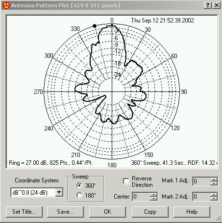
So what can you do with a CI-V interface? There are a number of logging and rig control programs which utilize the CI-V interface. One of the more interesting uses I have discovered involves antenna performance testing. Using a program called S-METER LITE by Seed Solutions, it is possible to use the CI-V port to transfer S-meter readings to the software, which can be used to draw antenna polar response plots! An example of such a plot is shown above. This plot shows the polar response of my horizontally polarized KLM 2M-16LBX yagi using a distant, vertically polarized signal source.