
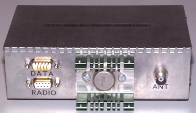
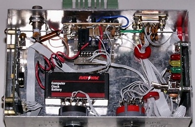
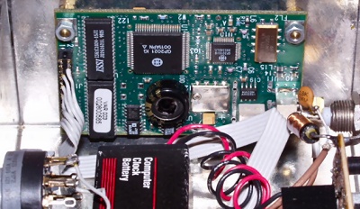
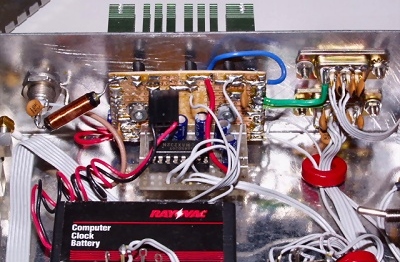
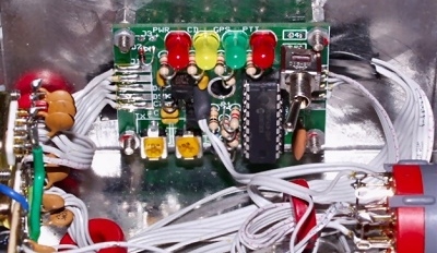
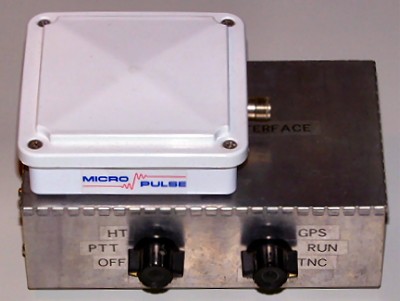
Front view. Switch on left turns unit on and off, and selects keying method: grounding PTT line for mobile rigs, or loading down mic line with a resistor for use with hand-helds. The TinyTrack can be used both ways, depending on whether a resistor or jumper is soldered in place during assembly. I wired the selector switch in place of the jumper, and remote mounted the resistor. Switch on right selects operating mode. RUN for normal operation; GPS to program GPS receiver or to output GPS data to use with external TNC; and TNC to program the TinyTrak3 or to use external GPS receiver with the tracker. Rear view. The female DB-9 marked RADIO connects to HT or mobile rig, and also supplies 12 VDC to the tracker. The male DB-9 connector marked DATA is used for programming the TinyTrack and GPS receiver parameters via serial port, as well as bi-directional data transfer, depending on setting of front-panel mode switch. Data connector also outputs NMEA GPS data stream when in RUN mode, to allow GPS data to be used for mapping and navigation programs on a laptop. BNC connector is RF input from amplified GPS antenna. The heatsink (an old 486 CPU cooler with fan removed and center milled out) and TO-3 device in center is the 5 VDC voltage regulator. Interior view. Marconi OEM GPS module is on left. 5VDC voltage regulator, power distribution bus, and TTL to RS-232 converter are located at top, between BNC and DB-9 connectors. TinyTrak3 TNC is located on right side, and GPS memory back-up battery is at center. Mode and keying selector switches are at bottom. Note the extensive use of RF bypass caps on DATA and RADIO DB-9 connectors, as well as torroid cores on cables. During initial testing, I found the TinyTrack3 TNC was particularly susceptible to RFI when the unit was used in close proximity to an HT. Adding caps and torroids eliminated the RFI problem. Close-up view of Marconi OEM GPS receiver module. I found this item on Ebay for $45. RF input from amplified GPS antenna in on lower right. Miniature double-row header on left outputs NMEA standard text at 4800 baud in TTL format. Large black circular item in center of board is a super-cap used for memory back-up for storing receiver configuration parameters and location information. Marconi states the cap is good for up to 5 days of back-up, so I added an external 4.5 volt lithium battery salvaged from my computer parts junk box. Small ceramic cap and choke on right form a bias-T for remote amplified GPS antenna. Close-up of voltage regulator and RS-232 converter. Voltage regulator drops 12VDC supply to 5VDC required by GPS receiver. Small plastic TO-92 devices at top are 300 mA solid-state circuit protectors, individually protecting various modules from overload or shorts. Ceramic DC blocking cap on BNC connector feeds RF to GPS receiver, while choke supplies DC power to amplified GPS antenna. The RS-232 converter uses a MAX-232 chip as a bi-directional TTL to RS-232 level converter to interface the GPS receiver's TTL output to RS-232 levels needed by the TNC and external data port, which is used to configure GPS receiver parameters, or for use with a laptop for mapping and navigation. Close-up of TinyTrak3 TNC. This item was purchased as a kit from BYONICS for about $30. Unit functions as a one-way TNC, converting data from GPS output to audio tones for 2 meter FM transmitter. TNC does not decode any received data- it simply monitors receiver audio for any noise on squelch break. Any audio received, whether valid APRS data or not, will trigger CD condition on TNC and inhibit transmission of data. Status LEDs along top indicate POWER, CARRIER DETECT, GPS DATA VALID, AND PTT conditions. Small pots adjust for transmit level and receive audio CD sensitivity. Toggle switch allows selection between 2 individually programmable configurations. Finished tracker shown with Micro-Pulse amplified GPS surveying antenna. The antenna, which was purchased on Ebay for $20, measures 4 inches square and includes a 40dB amplifier. Antenna is mounted on rear-deck of vehicle against base of rear window. Click here for a block diagram of the APRS position tracker.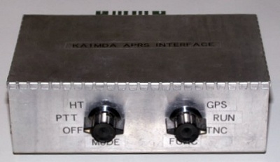
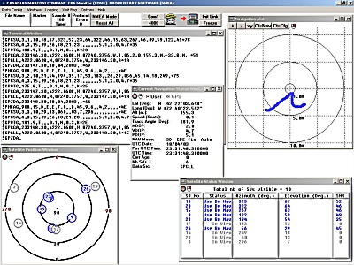
Screen shot of Windows configuration software supplied with the Marconi OEM GPS receiver. The software allows for selection of operating mode, receiver parameters, and I/O configuration. The software also allows realtime monitoring of various output parameters, including GPS raw data stream, satellite status & visibility, current location, time, and dillution of precision.
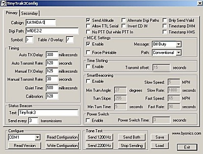
Screen shot of Windows configuration software supplied with the TinyTrak3 APRS TNC kit. Software allows for saving two distinct configurations, as well as teaking various radio and beaconing parameters. More info about the TinyTrak3 APRS TNC can be downloaded from BYONICS WEB SITE
Here's a screen capture of a little 7,400 mile road trip I took in the summer of 2004. The vehicle was equipped with a Garmin GPS receiver and a Kenwood 50 watt VHF transmitter which sent out position reports via the Amateur Radio APRS network every 3 minutes. When I got back, I went on line to the APRS server and had it plot every received position report from the 17 days of my trip on a Landsat map of North America. The gap in Nebraska is not an error- there was just no APRs or packet activity in Nebraska at all. To take a break from all the techno-babble, click on the map to see some photos from the trip.