BUILD THE KA1MDA
DYNAMIC COMPONENT ANALYZER
BUILD THE KA1MDA
DYNAMIC COMPONENT ANALYZER
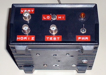
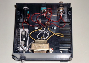
Commercial dynamic component analyzers are typically priced out of reach of the average electronics hobbyist. These analyzers work by applying a current-limited AC voltage across the device under test, and then displaying the resulting voltage/current signature on a CRT. If you already own an oscilloscope which allows for X-Y display, you've already got 99% of a dynamic component analyzer! The photos above show just how few components are needed to build the adapter!
I built the prototype dynamic component analyzer in 1991, and wrote a construction article about it for 73 Amateur Radio Today, which appeared in the May, 1992 issue. The full theory of operation, along with construction details can be seen in the original article. Click on the schematic diagram below to view the original construction article.
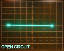
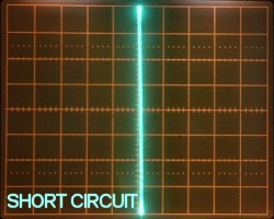
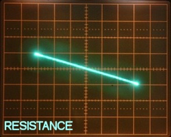
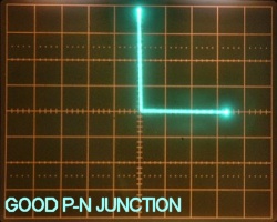
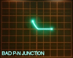
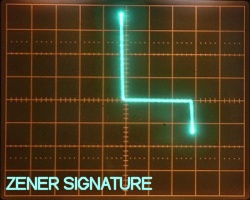
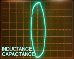
The images below are actual 'scope photos of typical traces one might see while using the dynamic component analyzer. I found the analyzer most useful for testing semiconductor device junctions, as it was far easier to spot leaky or bad P-N junctions (especially in power transistors) much more easily with the analyzer thasn with the standard DMM diode check test!